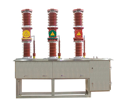
Model and Its Definition
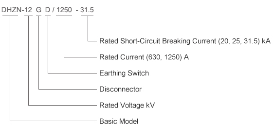 Note: If the earthing switch is not equipped, the earthing operating shaft shall serve as an interlock shaft, with the overall dimensions remaining unchanged.
Service Environment Conditions
Note: If the earthing switch is not equipped, the earthing operating shaft shall serve as an interlock shaft, with the overall dimensions remaining unchanged.
Service Environment Conditions
◆ Ambient temperature: -25℃ ~ +40℃
◆ Relative humidity: Daily average < 95%, monthly average < 90%
◆ Altitude: Not higher than 1000 m
◆ Seismic intensity: Not exceeding Grade 8
◆ Service location: Free from explosion hazards, chemical corrosion, severe vibration and pollution
◆ Service conditions for altitude above 1000 m
◆ When the altitude exceeds 1000 m, the air density will decrease relatively, which will affect the protection parameters of electrical equipment.
◆ The user must conduct relevant calculations when selecting the switch.
◆ Recommended calculation method:
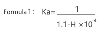
Determine the altitude H of the designated location, calculate the corresponding altitude correction factor Ka in accordance with the provisions of GB 311.1 (refer to Formula 1). Multiply the lightning impulse withstand voltage and power frequency withstand voltage of the switch by Ka; the resulting values are the withstand voltage parameters that the switch must meet when operating at the high altitude H and also when used in environments below 1000 m.
 Applicable Cabinet Types
It can be assembled in small-sized fixed cabinets, ring main units or packaged substations.
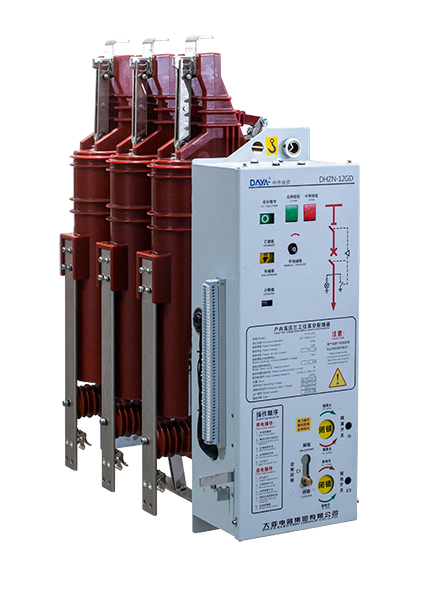
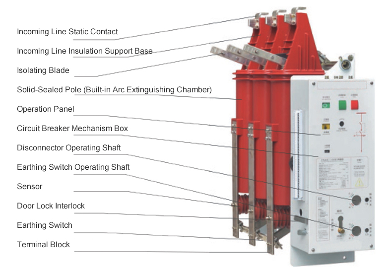
The main circuit of the DHZN-12GD series indoor high-voltage three-position vacuum circuit breaker is arranged vertically: the isolating switch is located at the upper part, the vacuum circuit breaker in the middle, and the earthing switch at the lower part. The operating mechanism, circuit breaker mechanism and interlocking mechanism are positioned at the front of the switch. This switch is suitable for inverted installation.
Safe and High-performance Solid-sealed Poles
High reliability, stable insulation performance, more robust structure, miniaturization, maintenance-free operation, enhanced environmental friendliness, and high mechanical resistance.
Visible Isolation Break Point
Rotary isolating switch with visible break points after opening.
Modular Operating Mechanism
The circuit breaker adopts a modular operating mechanism, which allows independent replacement or maintenance and features excellent interchangeability. It can be operated manually, or alternatively equipped with AC/DC energy storage operation to achieve remote control.
Three-axis Stepwise Operation, Reliable Mechanical Interlocking
The isolating switch, circuit breaker and earthing switch are operated by separate individual shafts. Forced mechanical interlocks are provided between the three shafts to prevent misoperation.
Non-contact live display sensors are equipped at the outlet terminals.
No capacitors, adopting non-contact induction technology, safe and reliable!
A reliable interlock structure is designed between the cabinet door and the connecting switch.
Ensure the operator's safety with an adjustment-free cabinet door locking device.
Technical Parameters
|
Item
|
Unit
|
Parameters
|
|
Rated Voltage
|
kV
|
12
|
|
(1 min) Rated short-time power-frequency withstand voltage: Phase-to-phase / Fracture
|
42/48
|
|
Rated lightning impulse withstand voltage (peak value): Phase-to-phase / Fracture
|
75/85
|
|
Power-frequency withstand voltage of secondary circuit (1 min)
|
V
|
2000
|
|
Rated Frequency
|
Hz
|
50
|
|
Rated Current
|
A
|
630 1250
|
|
Rated Short-Circuit Breaking Current
|
kA
|
20
|
25
|
31.5
|
|
Rated Peak Withstand Current
|
kA
|
50
|
63
|
80
|
|
Rated Short-Circuit Making Current
|
kA
|
50
|
63
|
80
|
|
4s Rated Short-Time Withstand Current
|
kA
|
20
|
25
|
31.5
|
|
Duration of Rated Short-Time Withstand Current
|
s
|
4
|
|
Rated Breaking Current for Single / Back-to-Back Capacitor Banks
|
A
|
630/400
|
|
Rated Capacitor Bank Closing Inrush Current
|
kA
|
12.5 (frequency not exceeding 1000 Hz)
|
|
Rated Short-Circuit Current Breaking Times
|
Times
|
30
|
|
Mechanical Service Life (Isolator 1 / Circuit Breaker / Earthing Switch)
|
|
3000/10000/3000
|
|
Allowable Cumulative Wear Thickness of Moving and Static Contacts
|
mm
|
3
|
|
Rated Common Operating Voltage
|
V
|
MC24/48/110/220 DC24/48/110/220
|
|
Rated Opening Operating Voltage
|
|
Rated Voltage of Energy Storage Motor
|
V
|
MC24/48/110/220 DC24/48/110/220
|
|
Rated Power of Energy Storage Motor
|
V
|
70
|
|
Energy Storage Time
|
s
|
≤ 15
|
|
Contact Opening Distance
|
mm
|
9 ± 1
|
|
Overshoot Travel
|
3.5 ± 0.5
|
|
Contact Closing Bounce Time
|
ms
|
≤ 2
|
|
Three-Phase Opening/Closing Asynchronism
|
≤ 2
|
|
Opening Time (Rated Voltage)
|
≤ 40
|
|
Closing Time (Rated Voltage)
|
≤ 60
|
|
Average Opening Velocity (at Initial Contact Separation, 6 mm)
|
m/s
|
0.9 ~ 1.3
|
|
Average Closing Velocity (6 mm ~ Initial Contact Making)
|
0.5 ~ 1.1
|
|
Contact Opening Rebound Amplitude
|
m
|
≤ 2
|
|
Contact Closing Contact Pressure
|
N
|
2400±200 ( 20 -25kA ) 3100+200 ( 31. 5kA )
|
|
Rated Operating Sequence
|
|
0-0.3s-CO-180s-CO
|
Configuration
Standard Configuration: Wired in accordance with the standard wiring schematic diagram, equipped with an anti-tripping device. Without a closing locking device, an overcurrent device, or an undervoltage device.
|
Configuration
|
Parameters
|
Remarks
|
|
Energy Storage Motor
|
75W
|
Standard Configuration
|
|
Closing Coil
|
A(D)C24~220V
|
Standard Configuration
|
|
Opening Coil
|
A(D)C24~220V
|
Standard Configuration
|
|
Disconnector Auxiliary Switch
|
1 NO + 1 NC, 5A
|
Standard Configuration
|
|
Earthing Switch Auxiliary Switch
|
1 NO + 1 NC, 5A
|
Standard Configuration
|
|
Energy Storage Mechanism Auxiliary Switch
|
2 NO + 1 NC, 5A
|
Standard Configuration
|
|
Circuit Breaker Auxiliary Switch
|
8 NO + 8 NC, 5A
|
Standard Configuration
|
|
Anti-tripping Device
|
A(D)C24~220V
|
Standard Configuration
|
|
Live Sensor (Inductive Type)
|
Non-contact Type
|
Standard Configuration
|
|
Locking Device
|
A(D)C24~220V
|
Optional Configuration
|
|
Overcurrent Release
|
3.5A、5A
|
Optional Configuration
|
|
Undervoltage Device
|
A(D)C24~220V
|
Standard Configuration
|
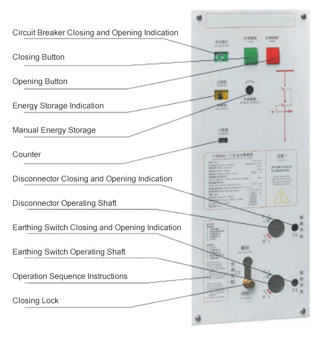
Referring to the switch operation indicator plate on the right, the instructions are as follows:
Double Interlock: For the circuit breaker, disconnector and earthing switch, a forced mechanical interlock is configured for operation. An anti-misoperation locking device is designed for the circuit breaker, disconnector and earthing switch to prevent incorrect operation.The disconnector and earthing switch are operated step by step via separate independent shafts respectively, and a forced mechanical interlock is installed between the two operating shafts. After opening and closing operations of the switches, please confirm their respective open/closed states through the observation window.
Interlock Between Circuit Breaker, Disconnector, Earthing Switch and Cabinet Door
◆ The disconnector and the earthing switch are equipped with a mutual forced mechanical interlock, which allows only one of the two devices to be closed and prohibits their simultaneous closing.
◆ The disconnector can only be closed after the earthing switch is opened; the earthing switch cannot be closed after the disconnector is closed.
◆ The circuit breaker can be closed only when the closing lock is in the locked position, while the disconnector and earthing switch are not operable under this condition.
◆ The circuit breaker cannot be closed when the closing lock is in the unlocked position, whereas the disconnector and earthing switch become operable.
◆ After the circuit breaker is closed, the closing lock cannot be unlocked, and the disconnector as well as the earthing switch are not operable.
◆ The cabinet door can only be opened after the earthing switch is closed.
◆ The earthing switch can only be opened after the cabinet door is closed.
 Operation of Closing Lock
1、Locking
Rotate the outer ring of the locking operation shaft by 90° (to release positioning), push it to the limit position in the locking direction, and then rotate the outer ring of the operation shaft by 90° again (to lock positioning).
2、Unlocking
Rotate the outer ring of the locking operation shaft by 90° (to release positioning), push it to the limit position in the unlocking direction, and then rotate the outer ring of the operation shaft by 90° again (to lock positioning).
Operation of the Circuit Breaker
Manual Operation
1、Use the dedicated energy storage handle for energy storage.
2、Closing: Press the closing button. (If equipped with a closing lock or undervoltage device, the secondary circuit must be powered on before closing can be performed)
3、Opening: Press the opening button.
Electric Operation
1、After the secondary circuit is powered on, the energy storage mechanism will store energy automatically.
2、Closing: Press the closing button in the control circuit.
3、Opening: Press the opening button in the control circuit.
Operation of the Disconnector
Clockwise rotation is for disconnector opening.
Counterclockwise rotation is for disconnector closing.
Operation of Cabinet Door Locking
Closing the cabinet door automatically releases the interlock between the cabinet door and the earthing switch. After the earthing switch is closed, if the cabinet door is opened, the earthing switch will be automatically locked and cannot be operated.
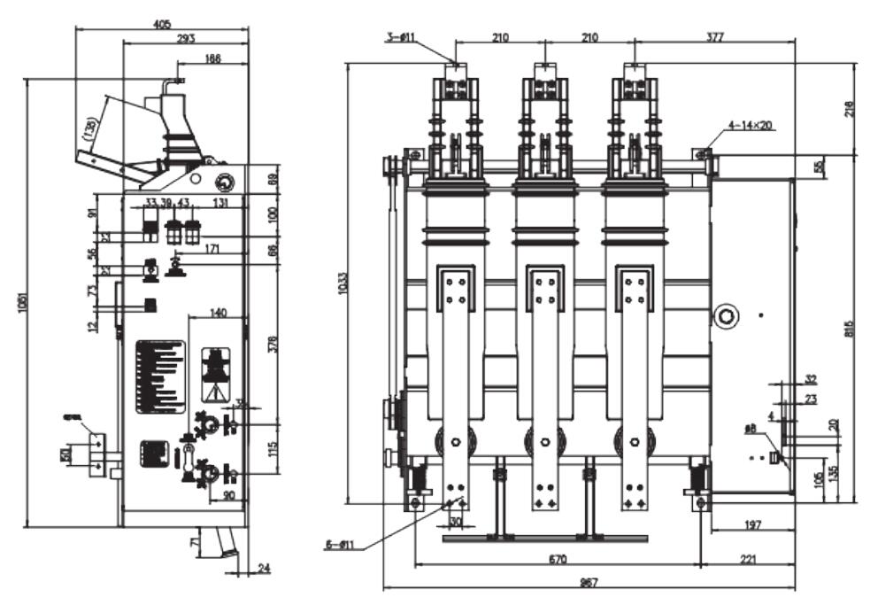
Overall and Mounting Dimensions (mm)