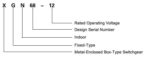
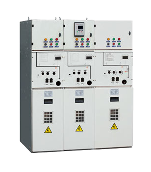
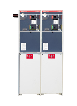
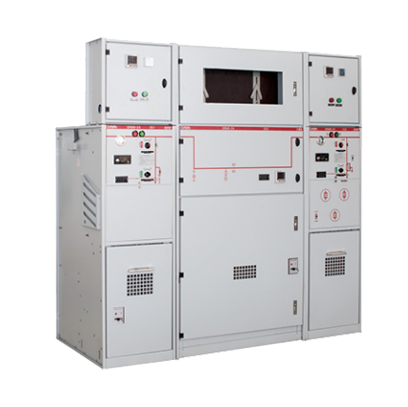
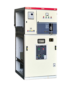
Model
Usage environment:
1、Altitude: ≤ 1000m
2、Ambient Temperature: -25℃ ~ 40℃
3、Relative Humidity: Daily average ≤ 95%, Monthly average ≤ 90%
4、Seismic Capacity: Seismic intensity not exceeding Grade 8
5、Installation Inclination: Inclination not exceeding 5 degrees
6、Service Location: No explosion hazard, no chemical corrosion, and no intense vibration
Main Technical Parameters:
|
No.
|
Parameter Name
|
Unit
|
Value
|
|
1
|
Rated Voltage
|
KV
|
12
|
|
2
|
Rated Current of Main Busbar
|
Hz
|
630
|
|
3
|
Rated Frequency
|
kA
|
50
|
|
4
|
Rated Short-Time Withstand Current of Main Circuit and Earthing Circuit
|
kA
|
20
|
|
5
|
Rated Short-Time Peak Current of Main Circuit and Earthing Circuit
|
kA
|
50
|
|
6
|
Rated Short-Time Making Current of Main Circuit and Earthing Circuit
|
kA
|
50
|
|
7
|
Fuse Breaking Current
|
kA
|
31.5 40
|
|
8
|
1-Minute Power Frequency Withstand Voltage (RMS Value): Phase-to-Phase, Phase-to-Ground / Isolating Breaks
|
kA
|
42/49
|
|
9
|
Lightning Impulse Withstand Voltage (Peak Value): Phase-to-Phase, Phase-to-Ground / Phase-Isolating Breaks
|
kA
|
75/85
|
|
10
|
Power Frequency Withstand Voltage of Secondary Circuit
|
V
|
2000
|
|
11
|
Rated Current Breaking Times
|
Times
|
10000
|
|
|
Mechanical Life
|
Circuit Breaker, Load Switch
|
Times
|
10000
|
|
Isolating Switch, Earthing Switch
|
Times
|
200
|
|
13
|
Enclosure Protection Rating (IP Rating)
|
|
IP2X
|
|
14
|
Operation Mode
|
|
Manual or Electric
|
|
15
|
Overall Dimensions
|
Circuit Breaker Cabinet
|
mm
|
400×800×1600
|
|
Load Switch Cabinet
|
mm
|
500×800×1600
|
Structural Characteristics of the Cabinet Body:
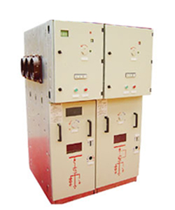
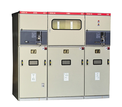
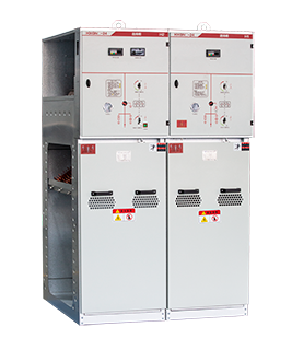
The switchgear is fabricated from 2mm-thick aluminum-zinc coated steel plates processed by CNC machine tools, featuring high precision, high strength, and an elegant appearance. Two pressure relief openings are provided at the rear of the cabinet to maximize personal safety and operational reliability.
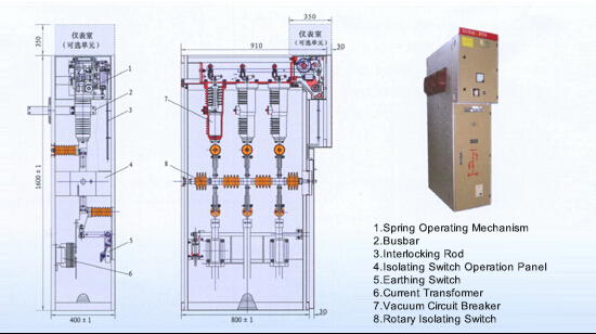
Schematic Diagram of the Circuit Breaker Cabinet Structure:
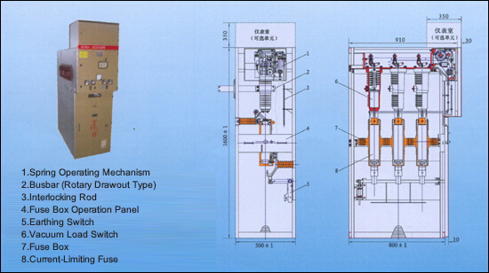
Schematic Diagram of the Load Switch Cabinet Structure: