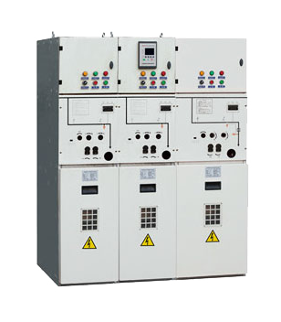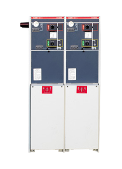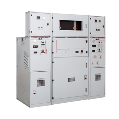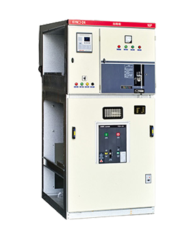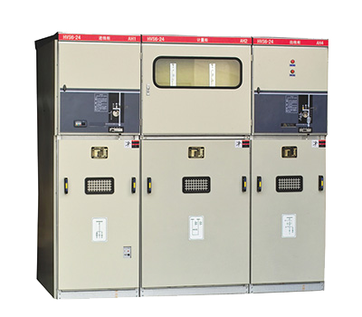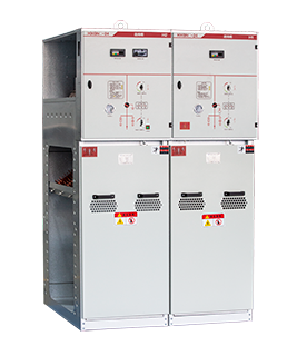
XGN2-10 Box type Fixed Metal Enclosed Switchgear
-
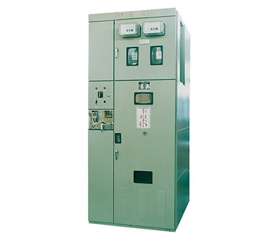
- Product Overview
- Type XGN2-10 is a box-type fixed metal-enclosed switchgear (hereinafter referred to as the "switchgear") with a rated voltage of 12kV. It is used in 50Hz three-phase AC systems with a voltage level of 12kV and below for receiving and distributing electrical energy, and is particularly suitable for occasions requiring frequent operations. Its busbar system includes single busbar and single busbar with bypass configurations. This switchgear complies with the requirements of GB3906 and IEC298, and is equipped with the "five-prevention" interlocking function specified by both standards. The combinations of circuit breakers and operating mechanisms configured for this switchgear are as follows: ZN12-10 matched with CT100 dedicated spring operating mechanism; ZN28-10 matched with CD10Ⅱ electromagnetic operating mechanism, CT8Ⅱ spring operating mechanism, and CT19 spring operating mechanism; SN10-10 (Type Ⅰ, Ⅱ) matched with CD10Ⅱ electromagnetic operating mechanism, CT8Ⅱ spring operating mechanism, and other series. In accordance with the requirements of fixed switchgears, the isolating switches adopted include GN30-10 rotary isolating switch and GN22-10 isolating switch series.
-
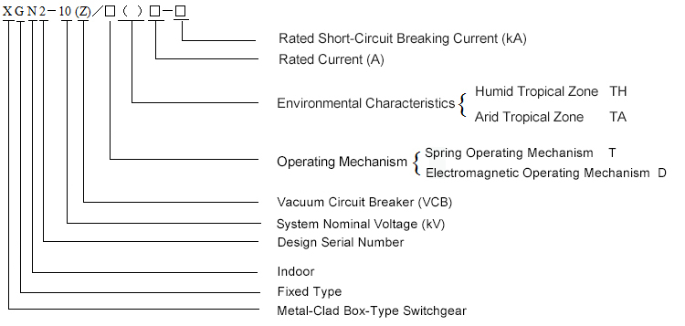
Model and Its Meaning
Normal Service Conditions
a) Indoor
b) Ambient Air Temperature: Upper limit +40℃; Lower limit -25℃
c) Altitude: Not exceeding 1000m (among which ZN28-10 equipped with CD10 or CT8 can reach 2500m)
d) Relative Humidity: Daily average not greater than 95%; Monthly average not greater than 90%.
e) Seismic Intensity: Not exceeding Grade 8
f) Locations free from fire, explosion hazards, severe pollution, chemical corrosion, and intense vibration.Note: For users operating beyond the above normal service conditions, corresponding measures can be negotiated with the manufacturer to meet specific requirements.Technical Parameters
Technical Parameters of the Switchgear (see Table 1)
Table 1
No.
Parameters Name
Unit
Parameters
1
Rated Voltage
kV
3.6 , 7.2 , 12
2
Rated Current A
630,1000,1600,2000,3150
3
Rated Frequency Hz
50
4
Rated Insulation Level
Lightning Impulse Withstand Voltage Phase-to-Phase and Phase-to-Ground
kV
75
Isolating Breaks
85
1-Minute Power Frequency Withstand Voltage
Phase-to-Phase and Phase-to-Ground
42
Isolating Breaks
48
5
Rated Short-Time Withstand Current kA
20
31.5
40
6
Rated Peak Withstand Current kA
50
80
100
7
Rated Short-Circuit Making Current kA
50
80
100
8
Rated Short-Circuit Breaking Current kA
20
31.5
40
9
Rated Short-Circuit Duration s
4
10
Protection Class
IP2X
11
Busbar System
Single Busbar (Single Busbar with Bypass) 12
Operating Mode
Electromagnetic Type or Spring Energy Storage Type 13
Overall Dimensions of Various Cabinet Types (Width × Depth × Height)
mm
Small Current Cabinet (1600A and below): 1100×1200×2650
Large Current Cabinet (above 1600A): 1200×1200×2650
Overhead Outlet Cabinet: 1100(1200)×1600×2650
Single Busbar with Bypass: 1100(1200)×1900×2650Technical Parameters of the Circuit Breaker (see Table 2)
Table 2
No. Parameter Name Unit SN10-10
ZN28-10
ZN12-10
1
Rated Voltage kV
10
2
Rated Frequency Hz
50
3
Rated Current A
630,1000
1250,1600
1250,1600,3150
4
Rated Short-Circuit Breaking Current kA
16,31.5
31.5
31.5,40
5
Rated Short-Circuit Making Current (Peak) kA
40,80
80
80,100
6
Rated Peak Withstand Current kA
40,80
80
80,100
7
Rated Short-Time Withstand Current kA
16,31.5
31.5
31.5,40
8
Rated Short-Circuit Duration s
4
9
Mechanical Life Times
2000
10000
10
Rated Short-Circuit Breaking Times 20
30
Main Technical Parameters of the Operating Mechanism (see Tables 3 — 6)
Table 3 Main Technical Parameters of CD10Ⅱ DC Electromagnetic Operating Mechanism
No. Parameters Name
Unit CD10Ⅱ
1
Rated Voltage Closing Coil
V
110,220
Opening Coil 24,48,110,220
2
Rated Current Closing
110
A
240
220
240
Opening
24
37
48
18.5
110
5
220
2.5
Table 4 Main Technical Parameters of CT100 Dedicated Spring Operating Mechanism
No. Parameters Name Unit
Data
1 Power Supply Voltage of Energy Storage Motor V
—~110,—~220
2
Voltage of Opening and Closing Electromagnets —~110,—~220
3
Voltage of Under-Voltage Release —~110,—~220
4
Energy Storage Time s
≤15
5
Rated Current of Over-Current Release A
2.5
Table 5 Main Technical Parameters of CT8Ⅱ Spring Operating Mechanism
No. Parameters Name Unit
Data
1
Power Supply Voltage of Energy Storage Motor V
—~110,—~220, ~380
2
Voltage of Opening and Closing Electromagnets —~110,—~220,~380,—48
3
Voltage of Under-Voltage Release ~110,~220,~380
4
Energy Storage Time s
≤5
5
Rated Current of Over-Current Release A
5
Table 6 Main Technical Parameters of CT19 Spring Operating Mechanism
No. Parameters Name Unit
Data
1
Power Supply Voltage of Energy Storage Motor V
—~110,—~220
2
Voltage of Opening and Closing Electromagnets —~110,—~220,~380,—48
3
Voltage of Under-Voltage Release —~110,—~220,~380,—48
4
Energy Storage Time s
≤10
5
Rated Current of Over-Current Release A
5
Technical Parameters of the Isolating Switch (see Table 7)
Table 7
No.
Parameters Name Unit GN30-10
GN30-10DGN30-10
GN30-10D
GN30-10
GN30-10DGN22-10 GN22-10
1
Rated Voltage kV
10
2
Rated Current A
400
630
1000
2000
3150
3
Rated Peak Withstand Current kA
31.5
50
80
100
105
4
Rated Short-Time Withstand Current kA
10.5
20
31.5
40
50
5
Rated Short-Circuit Duration s
4
6
Lightning Impulse Withstand Voltage kV
Phase-to-Phase and Phase-to-Ground:75,Isolating Breaks :85
7
Short-Time Power Frequency Withstand Voltage Phase-to-Phase and Phase-to-Ground:42,Isolating Breaks :48
Technical Data of the Earthing Switch (see Table 8)
Table 8
No.
Name
Unit
JN2-10
1
Rated Voltage kV
10
2
Lightning Impulse Withstand Voltage 75
3
4-Second Thermal Stability Current kA
31.5
4
Dynamic Stability Current 80
5
1-Minute Power Frequency Withstand Voltage kV
42
Technical Parameters of the Current Transformers (see Tables 9—10)
Table 9 Technical Parameters of LZBJ12-10 Current Transformer
Rated Primary Current (A) Secondary Current (A) Rated Short-Time Thermal Current (kA) Dynamic Stability Current (kA) Rated Secondary Load (VA) Accuracy Limit Factor for Class 10P (Times) Class 0.5, Class 1 Class 10P 5
5
2
5
10
15
10
10
4
10
15
6
15
20
8
20
30
10
25
40
16
40
50
20
50
75
33
80
100~300
45
100
400~800
45
100
1000~1500
63
130
Table 10 Technical Parameters of LMZJ1-10 Current Transformer
No.
Parameters Name Unit
Data
1
Rated Primary Current (A) A
2000,3150,4000
2
Secondary Current (A) 5
3
Rated Frequency Hz
50
4
Rated Secondary Load Class 0.5 VA
50
Class 10P 60
5
Accuracy Limit Factor for Class 10P Times 15
Technical Data of the Voltage Monitoring Device (see Table 11)
Table 11
No.
Name
Unit
ZDJ□-6
ZDJ□-10
DXN3-4
1
Rated Voltage kV
6
10
10
2
Lightning Impulse Withstand Voltage 57
75
75
3
Short-Time Power Frequency Withstand Voltage (1min) 32
42
42
4
Minimum Ignition Voltage of Neon Lamp (Primary Voltage) 3
5
5
5
Maximum Operating Voltage of Neon Lamp (Primary Voltage) 7.2
12
12
Technical Parameters of the Arrester (see Table 12)
Table 12
Model
Voltage
HY2.5W1
-7.6/19
HY2.5W1
-12.7/31
HY5WR2
-10/27
HY5WR2
-17/45
HY5WZ2
-10/27
HY5WZ2
-17/45
HY5WS2
-10/30
HY5WS2
-17/50
Purpose
Motor Type Capacitor Type Power Station Type Distribution Type System Rated Voltage kV
6
10
6
10
6
10
6
10
Arrester Rated Voltage kV
7.6
12.7
10
17
10
17
10
17
Residual Voltage (8/20)μs 5kA kV
≤19
≤31
≤27
≤45
≤27
≤45
≤30
≤50
Arrester Continuous Operating Voltage kV
4
6.6
7.6
12.7
7.6
12.7
7.6
12.7
Structural Characteristics
Components (see Figures 3, 4, 5, 6):
This switchgear adopts a metal-enclosed box-type structure. The cabinet frame is fabricated by bending and welding angle steel and steel plates, and the interior is divided into a circuit breaker compartment, a busbar compartment, a cable compartment, and a relay compartment. Each compartment is separated by steel plates. The switchgear supports double-sided maintenance: from the front, secondary components in the relay compartment can be inspected, the operating mechanism, mechanism interlocks, and transmission parts can be maintained, and the circuit breaker can be overhauled; from the rear, the main busbar and cable terminations can be maintained. Lighting lamps are installed in both the circuit breaker compartment and the cable compartment. A grounding copper busbar parallel to the cabinet width direction is provided at the lower part of the rear door, with a cross-sectional area of 4×40mm².
Circuit Breaker Compartment:
The circuit breaker compartment is located at the lower part of the cabinet. The transmission of the circuit breaker compartment is connected to the operating mechanism via a pull rod; the lower terminals of the circuit breaker are connected to the current transformers, which are in turn connected to the terminals of the lower isolating switch. The upper terminals of the circuit breaker are connected to the terminals of the upper isolating switch. Additionally, the circuit breaker compartment is equipped with a pressure relief channel. In the event of an internal arc fault, gas can release pressure through the exhaust channel.
Busbar Compartment:
The busbar compartment is located at the rear upper part of the cabinet. To reduce the cabinet height, the busbars are arranged in a delta (Δ) configuration and supported by porcelain insulators, with the busbars connected to the terminals of the upper isolating switch.
Cable Compartment:
The cable compartment is located at the rear lower part of the cabinet. The supporting insulators inside the cable compartment can be equipped with probes for the voltage monitoring device, and the cables are fixed on brackets. When the main wiring adopts an interconnection scheme, this compartment functions as an interconnection cable compartment.
Instrument Compartment:
The instrument compartment is located at the front upper part of the switchgear. It is designed for installing secondary instruments, and terminals for mounting through-type secondary small busbars are provided at the top. The overall dimensions of the instrument compartment are (Width × Height × Depth) 1100×850×250 mm. Instruments are mounted on three door panels with dimensions (Width × Height) 300×700 mm, 720×700 mm, and 780×580 mm respectively.
Misoperation Prevention Interlocking Device:
The operating mechanism of the circuit breaker is installed on the left side of the front panel. Above it is the operating and interlocking mechanism (model: JSXGN) of the isolating switch, which adopts a forced mechanical interlock with the operating mechanism. The front and rear doors are controlled by program locks. The entire interlocking system follows a specific sequence—operations must be performed in the prescribed order; otherwise, operation is prohibited. The detailed operating principle is as follows:
Power Shutdown Operation (Running → Maintenance)
The switchgear is in the working position: the upper and lower isolating switches and the circuit breaker are closed, the front and rear doors are locked, and the equipment is in live operation. At this time, the small handle is in the "Working" position.
First, open the circuit breaker, then switch the small handle to the "Open Lockout" position (the circuit breaker cannot be closed afterward). Insert the operating handle into the isolating switch's operation hole and pull downward to the isolating open position (the sequence of operating the upper or lower isolating switch is user-definable). Remove the operating handle, insert it into the earthing switch's operation hole, and push upward to close the earthing switch. At this point, the small handle can be switched to the "Maintenance" position, allowing the front door to be opened. Take the key to unlock the rear door. The power shutdown operation is completed, and maintenance personnel may perform maintenance and overhaul on the circuit breaker and cable compartment.
Power Transmission Operation (Maintenance → Running)
If the maintenance has been completed and power transmission is required, the operating procedure is as follows:
Close and lock the rear door, remove the key, then close the front door. Switch the small handle from the "Maintenance" position to the "Open Lockout" position—at this point, the front door is locked and the circuit breaker cannot be closed. Insert the operating handle into the earthing switch's operation hole and pull downward to place the earthing switch in the open position. Remove the operating handle, insert it into the isolating switch's operation hole, and push upward to close the isolating switch (the sequence of operating the upper or lower isolating switch is user-definable). Extract the operating handle and switch the small handle to the "Working" position. The circuit breaker can now be closed to put the equipment into operation.
Pressure Relief Device:
Pressure relief channels are installed in the circuit breaker compartment, busbar compartment, and cable compartment of the switchgear. In the event of an internal arc fault, gas can release pressure through the exhaust channels.
Similar Products
-