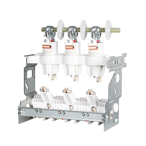
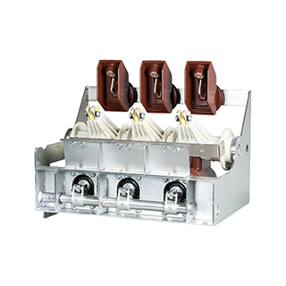
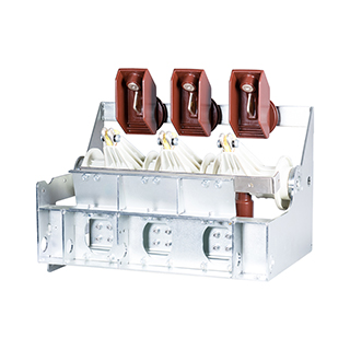
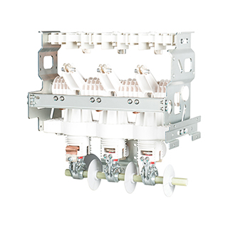
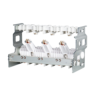
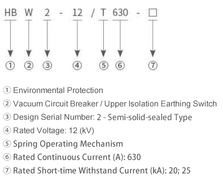
Model Designation and Its Interpretation
 Executed Standards
GB/T 1984 High-voltage Alternating Current Circuit Breakers
DL/T 402 High-voltage Alternating Current Circuit Breakers
GB/T 1985 High-voltage Alternating Current Isolators and Earthing Switches
DL/T 486 High-voltage Alternating Current Isolators and Earthing Switches
Notes on Ambient Operating Conditions
Altitude shall not exceed 2000 m; seismic withstand capacity (horizontal acceleration) is 2 m/s².
The ambient air temperature shall not exceed +50°C, and the minimum temperature measured within 24 hours shall not be lower than -40°C.
It is not suitable for use in locations with frequent severe vibrations, locations where water vapor, gases, chemical corrosive deposits, salt mist, dust and dirt that obviously affect performance exist, as well as explosive and fire-hazardous environments.
Technical Parameters
|
Rated Voltage
|
12kV
|
|
Rated Continuous Current
|
630A
|
|
Rated Frequency
|
50Hz
|
|
Rated Short-Circuit Breaking Current
|
20; 25 (kA)
|
|
Rated Short-Circuit Making Current (Peak Value)
|
50; 63 (kA)
|
|
Capacitive Current Making and Breaking Test
|
Class C2
|
|
Rated Operating Sequence
|
0-0.3s-CO-180s-CO
|
|
Rated Short-Time Withstand Current (RMS Value) and Duration
|
Main Circuit / Earthing Switch
|
20/4; 25/4 (kA/s)
|
|
Earthing Connection Circuit
|
17.4/2; 21.75/2 (kA/s)
|
|
Rated Peak Withstand Current
|
Main Circuit / Earthing Switch
|
50; 63 (kA)
|
|
Earthing Connection Circuit
|
43.5; 54.8 (kA)
|
|
Mechanical Endurance
|
Circuit Breaker
|
10000/M2 (Times)
|
|
Disconnector / Earthing Switch
|
5000 (Times)
|
|
Electrical Endurance
|
Number of Rated Short-Circuit Current Breaking Operations of Circuit Breaker
|
30/E2 (Times)
|
|
Making Capacity for Earth Fault Short-Circuit
|
5/E2 (Times)
|
|
Insulation Test
|
Power Frequency Withstand Voltage of Main Circuit for 1 Minute:
Phase-to-Phase, Phase-to-Earth / Fracture Port
|
42/48 (kV)
|
Lightning Impulse of Main Circuit (12/50us)
Withstand Voltage: Phase-to-Phase, Phase-to-Earth / Fracture Port
|
75/85 (kV)
|
|
Power Frequency Withstand Voltage of Auxiliary Control Circuit for 1 Minute
|
2 (kV)
|
|
Control Voltage of Auxiliary Circuit(V)
|
24、48、110、220DC
|
|
110、220AC
|
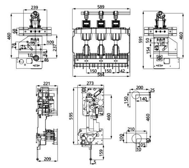
Overall and Mounting Dimensions
Operation Procedure for Upper Isolation Scheme
Power Failure and Earthing Operation
Initial Product State: The circuit breaker is in the closed position, the disconnector is in the closed position, and the earthing switch is in the open position.
Operation Steps: First, operate the circuit breaker to the open position → After confirming the circuit breaker is in the open position, operate the disconnector to the open position → After verifying the circuit is de-energized by voltage testing, operate the earthing switch to the closed position → Close the circuit breaker to achieve line-side earthing → Open the cable compartment door.
Power Restoration Operation
Initial Product State: The circuit breaker is in the closed position, the disconnector is in the open position, and the earthing switch is in the closed position.
Operation Steps: Close the cable compartment door → First, operate the circuit breaker to the open position → Operate the earthing switch to the open position → After confirming it is in the open position, operate the disconnector to the closed position → Confirm the disconnector is in the closed position → Close the circuit breaker.